Home » Without Label » 3 Way Switch Wiring / 3 Way Switch Troubleshooting Youtube / In houses, switches should always be mounted vertically (up and down).
3 Way Switch Wiring / 3 Way Switch Troubleshooting Youtube / In houses, switches should always be mounted vertically (up and down).
3 Way Switch Wiring / 3 Way Switch Troubleshooting Youtube / In houses, switches should always be mounted vertically (up and down).. It is really simple to attract a wiring diagram; Three way switch wiring with light middle the source in this circuit is at the first switch and the light fixture is located between sw1 and sw2. Take a closer look at a 3 way switch wiring diagram. All three switches are connected together by a three core and earth control cable. The circuit consists of a two way switch at each end (top and bottom switches in fig 2) and an intermediate switch in the middle.
It shows the parts of the circuit as simplified forms, as well as the power and signal connections in between the tools. 3 way switch wiring diagram. At the switch where you found power in step 2, put the other 2 wires you removed from the switch together and wire nut them. The other 2 wires can go on either of the two remaining screws. The white wire becomes the energized switch leg, as indicated by using black or red electrical tape.
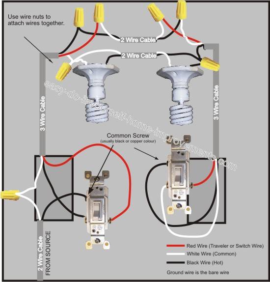
3 Way Switch Wiring Diagram from www.easy-do-it-yourself-home-improvements.com Set the electrical tester to the continuity or ohms setting. The only items not visible in the image are the switch blades, shown as purple in the. Video includes the bonus addition of addi. Standard 2 way switch wiring. This is a basic 3 way switch wiring method. C) the wires from the power source go from switch to switch, and then go to the light. It is the best and easiest method of wiring 3 way switches. The white wire of the cable going to the switch is attached to the black line in the fixture box using a wire nut.
The ground wire is pigtailed with a wire connector at the switch boxes and the ceiling box.
The 3 wire cable enters through the top of the first switch box. 3 way switch wiring diagram. It is the best and easiest method of wiring 3 way switches. With these diagrams below it will take the guess work out of wiring. The wiring diagram is normally made use of in electrical design to plan the positioning of electric circuits. All three switches are connected together by a three core and earth control cable. Touch the probes to the 3 wires removed from the switch until you get a reading on the tester indicating continuity. The white wire becomes the energized switch leg, as indicated by using black or red electrical tape. You simply need to have a good comprehension on various kinds of wiring and also their functions. In this case, electricity flows through the ceiling box from the first switch to the second switch. C) the wires from the power source go from switch to switch, and then go to the light. Notice that the wire connected to the com terminals is looped straight through. Assortment of fender telecaster 3 way switch wiring diagram.
In this configuration, the power enters the first switch, and the light fixture is placed after the second switch. Standard 2 way switch wiring. Three way switching schematic wiring diagram. In houses, switches should always be mounted vertically (up and down). It is the best and easiest method of wiring 3 way switches.
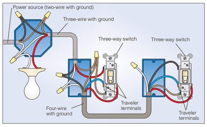
How To Wire A 3 Way Light Switch Diy Family Handyman from www.familyhandyman.com Three way switching schematic wiring diagram. Touch the probes to the 3 wires removed from the switch until you get a reading on the tester indicating continuity. This is a basic 3 way switch wiring method. You can observe in the schematic that both the com terminals are connected together. Now go the other switch location. In this configuration, the power enters the first switch, and the light fixture is placed after the second switch. The hot source wire is connected to the common terminal on sw1. The circuit consists of a two way switch at each end (top and bottom switches in fig 2) and an intermediate switch in the middle.
It is the best and easiest method of wiring 3 way switches.
In this configuration, the power enters the first switch, and the light fixture is placed after the second switch. Now go the other switch location. Pick the diagram that is most like the scenario you are in and see if you can wire your switch! Notice that the wire connected to the com terminals is looped straight through. It shows the parts of the circuit as simplified forms, as well as the power and signal connections in between the tools. The ground wire is pigtailed with a wire connector at the switch boxes and the ceiling box. The white wire becomes the energized switch leg, as indicated by using black or red electrical tape. 3 way switch wiring diagram. This might seem intimidating, but it does not have to be. Red wire (traveler or switch wire). Take a closer look at a 3 way switch wiring diagram. This is a basic 3 way switch wiring method. The hot source wire is connected to the common terminal on sw1.
The white wire of the cable going to the switch is attached to the black line in the fixture box using a wire nut. In houses, switches should always be mounted vertically (up and down). In the 3 way configuration depicted on this page, the white wire going from the fixture to switch 1 and the white wire going from switch 1 to switch 2 have been used to carry a switched ungrounded conductor (hot) part of the circuit and therefore as stated should have a piece of black electrical tape wrapped around that wire in the box. With these diagrams below it will take the guess work out of wiring. 3 way switch wiring diagram.
3 Way Switch Wiring Methods Electrician 101 from electrician101.files.wordpress.com 3 way switch wiring diagram. C) the wires from the power source go from switch to switch, and then go to the light. It shows the parts of the circuit as simplified forms, as well as the power and signal connections in between the tools. The white wire of the cable going to the switch is attached to the black line in the fixture box using a wire nut. This might seem intimidating, but it does not have to be. Set the electrical tester to the continuity or ohms setting. You simply need to have a good comprehension on various kinds of wiring and also their functions. The hot source wire is connected to the common terminal on sw1.
This might seem intimidating, but it does not have to be.
3 way switch wiring diagram. Three way switching schematic wiring diagram. The wiring diagram is normally made use of in electrical design to plan the positioning of electric circuits. At the switch where you found power in step 2, put the other 2 wires you removed from the switch together and wire nut them. The hot source wire is connected to the common terminal on sw1. It is the best and easiest method of wiring 3 way switches. With these diagrams below it will take the guess work out of wiring. You simply need to have a good comprehension on various kinds of wiring and also their functions. A wiring diagram is a simplified conventional photographic depiction of an electrical circuit. The only items not visible in the image are the switch blades, shown as purple in the. The ground wire is pigtailed with a wire connector at the switch boxes and the ceiling box. Wire this switch (#1) back up and put it back into the box. It shows the parts of the circuit as simplified forms, as well as the power and signal connections in between the tools.